AvCall
Aviation SELCAL-32 Decoder

Using ComTekk AvCall
1. Running ComTekk AvCall
Once ComTekk AvCall has been successfully installed, you may simply double-click the AvCall desktop icon or Click the Windows Start menu, then Programs, choose the ComTekk folder, then AvCall.
To control AvCall:
- To run the program, click the desktop icon or go to Start->Programs->ComTekk->AvCall .
- The top dot-matrix display indicates the current program status. A green "Ready" shows the decoder is running and listening for tones. VU meter indicates the presence of audio.
- Click the "POWER" button or "X" button in the upper-right corner of the window to close the application completely.
Continue on to Section 2 below for detailed description of the buttons and screens.
2. The AvCall User Interface
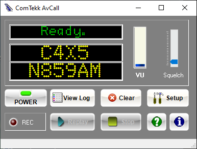
Controls:
1. POWER - Close / Exit the program
2. Replay - If enabled, this button will replay the last recording. WAV recording must be enabled in Settings. Button will be enabled after the first recording is complete.
3. Stop - Stops playback.
4. Squelch - sets the relative signal level detection threshold, so background noise or weak signals can be rejected. The default setting should work for most applications.
5. Setup - Opens the program Settings window (preferences).
6. ![]() Help - Opens the User Manual (this file)
Help - Opens the User Manual (this file)
7. ![]() About -Opens the program information screen, and Product Registration.
About -Opens the program information screen, and Product Registration.
8. View Log - Opens the current log file for viewing.
Indicators:
1. VU Meter - Analog meter display gives an easy-to-read indication of relative audio input level. This is handy for setting receiver and software volume controls. The level should be somewhere in the mid-range when radio traffic is being received.
If there is no indication on the VU meter, it is likely the wrong input is selected, or level is too low. See Setup section below.
2. Mode Display - The top-most dot-matrix display gives the current program status, such as "Ready", "Calibrating", "Decoding".
3. Data Displays - The two lower dot-matrix displays show SELCAL code and aircraft registration number (if found).
4. Status Bar - Located at the very bottom of the program window, gives additional information such as file names, recording & logging status, etc.
5. REC - Audio recording indicator, glows red while recording is active.
3. Settings Window
Audio Tab :
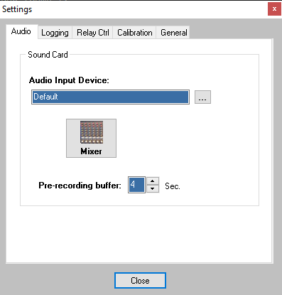
1. Audio Input Device - Select the input (recording) device [Windows Vista/7], or sound card [XP, NT, 2000, 98] to be used as the audio source. Click the button at right to modify this setting
2. Mixer - Opens the Windows Recording Control [XP, NT, 2000, 98], or Recording Device properties [Vista/7] to set the default recording device and input level.
3. Close - Closes the Settings Window. All settings are saved when program is exited.
3. Pre-recording buffer - Use to capture audio prior to the tones being deocded, i.e. to include the tones in your recording, set this value to 4 seconds or more.
Logging Tab:
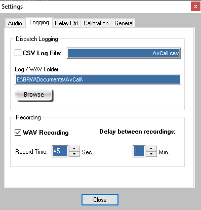
1. CSV Log File - Name of the log file, stored in "Comma-Separated Values" format, which is compatible with Microsoft Excel, and others. Click the checkbox to enable or disable logging.
2. Log/WAV Folder - Destination folder where log files and audio recordings will be stored. A dedicated folder is highly recommended.
3. Browse button - Opens a file explorer window containing logs and recording files.
Recording:
1. WAV Recording - When box is checked, enables audio recording of decoded radio calls. WAV files will be stored in the Log/WAV Folder selected above.
2. Record Time - Duration of audio recording [in seconds], starts immediately after the last tone is decoded.
3. Delay between recordings - Prevents recording duplicate or repeated tone-outs, which are often sent twice as a policy.
Calibration Tab:
1. Auto-Calibrate - Calibration is not required, and in most cases not necessary. This step need only be performed once, unless you change to a different sound card. See calibration section below.
2. Cal Factor - Resulting time-base correction multiplier after calibration is complete. A value of 1.0 is default, uncalibrated.
3. Reset - Returns calibration to the default uncalibrated state.
Relay Control Tab:
This feature may be used to change receive modes on a receiver (if equipped), activate a light, bell or other electrical device whenever ANY tones are decoded.
An external serial (RS-232) or USB relay adaptor is required to utilize this feature.
1. Control Port - feature is enabled when a valid serial port is selected (COM1 ~ COM64 supported). If selected port is not available, drop-down will return to the <OFF> position.
2. Control Pin - Select DTR (pin-4) or RTS (pin-7) control pin.
Standard DB-9 serial connections as seen on the back of a computer
3. Active State - determines whether the pin's voltage when activated by the decoder. Select High for positive voltage (+) or Low for negative (-).
4. Hold Time - the time in seconds that the serial pin will remain active. If set to 10 seconds and relay is connected to a bell, the bell will ring for 10 seconds every time tones are successfully decoded.
5. Test button - Click and hold to cause selected serial port/pin to be activated. Release mouse button to deactivate.
NOTE: Always use an isolated external circuit to protect computer from possible damage.
General Tab:
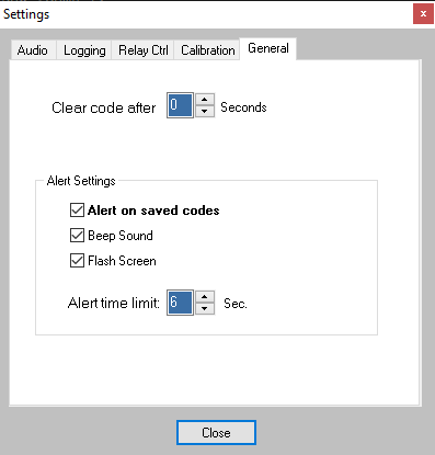
1. Clear code - When set to a value greater than zero, the received code display will clear after number of seconds selected [0..99].
2. Alert on saved codes - Enable this option to provide an audio-visual alarm when a code saved in your selcals.csv file is matched.
Please note the code must match exactly.
3. Beep Sound - Plays the Windows default sound when a matching code is received.
4. Flash Screen - The AvCall screen will flash red during an alert.
4. Alert time limit - Determines how long the audio-visual alert will repeat.
4. Windows Mixer Controls
Windows Volume Control (Output): [Windows 95, 98, NT, XP, 2000, ME] - scroll down for 7/Vista.
This screen controls the sound card OUTPUTS and will generally have no effect on the decoder, since it uses the sound card INPUTS, which are controlled by the Recording Control (see next section below).
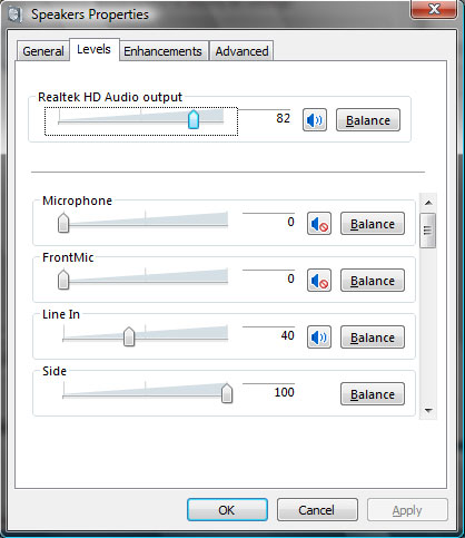
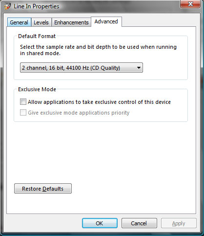
Windows Vista/7 playback [output] settings, accessible from Windows Control Panel
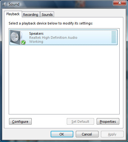
Click "Properties" then select the "Levels" tab for output mixer controls. Again, these controls will have NO effect on the decoder's operation:
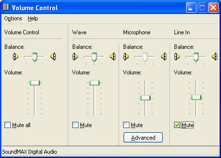
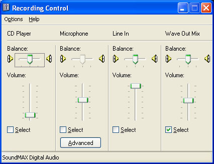
The Windows Recording Control [Windows 95, 98, NT, XP, 2000, ME] - affects sound device INPUTS, such as LINE , AUX, Wave, or Microphone. 7/Vista users, scroll down.
To access Recording controls, click the Mixer button in the Settings window, or with a double-click on the speaker icon in your system tray. Select "Options" from the menu, then "Properties." Click the "Recording" radio button. Be sure the appropriate input item is checked. Settings will be saved on closing this window.
It is very important to have the correct input device enabled, otherwise the decoder will not function.
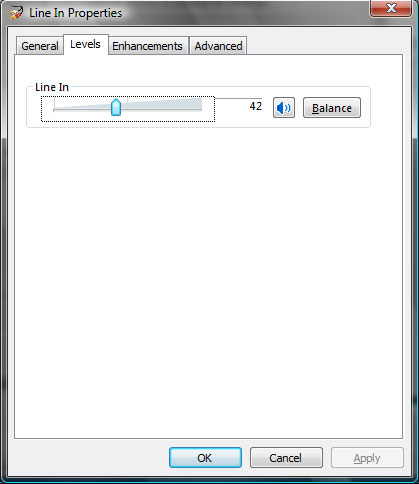
For Windows Vista/7 users, click the Mixer button in the Settings window. Line In is selected in the example below.
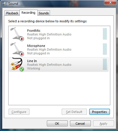
Click "Properties" then select the "Levels" tab for Line In level control. This sets the audio level sent to the Tone Decoder. Adjust this level while there is activity on the receiver. Monitor the decoder's VU meter, and set for a mid-range indication.
Additionally, the program may be given exclusive control of the selected device by checking the box below. This prevents the user from accidentally changing settings for this device. While not required, this option may be helpful in some situations.
5. Calibration
NOTE: Calibration is NOT required, but may improve results in some cases
Computer sound cards vary greatly in quality and design. They have their own time-base which controls the A/D and D/A sampling rate, which in turn directly affects the frequency. The calibration routine allows for compensation for timebase error, thus allowing more accurate frequency decoding.
ComTekk AvCall includes auto-calibration, which does not require any specialized equipment. However, a FULL-DUPLEX sound card is required. This means the card has the ability to play and record simultaneously. Virtually all modern sound cards are full duplex.
NOTE: Calibration need only be performed once for a particular sound card.
CALIBRATION INSTRUCTIONS:
1. Loop the sound card OUTPUT back to its INPUT. Three different ways to do this are presented below:
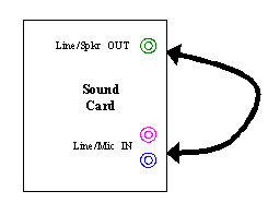
Option1: [above] Use a 1/8" stereo cable to connect
Line/Speaker OUT to
Line/Aux/Mic IN.
Option 2: Click the "Vol" button to open the Windows Recording Control. Select the "Wave Out Mix" (or similar) checkbox to create an internal loopback. Not all sound card drivers have this option. If available, it negates the need for an external connection.
Option 3: Audio pickup - If you have a microphone connected to (or internal to) your computer, Click the "Vol" button to open the Windows Recording Control. Select the "Microphone" checkbox to enable the MIC input. Place the microphone directly in front of a computer speaker so it will pick up the sound from the tone generator. Take care not to get it too close which will generate feedback, voiding the calibration.
2. Once the loopback is established using one of the methods described above, Click the "Calibrate" button to begin.
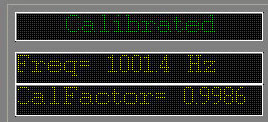
If using speakers and loopback is working, you should hear a very short tone. The Status will change to "Calibrated" and the frequency and calibration factor will be displayed. The VU meter will indicate relative INPUT level. It may be necessary to adjust input or output levels, or the microphone position if using Option 3 for loopback.
The measured frequency should be somewhere close to 1,000 Hz. If it is closer to 2,000 Hz, the volume and/or input level is most likely too high.
If the calibration tone was not detected, this will be indicated on the "Status" line. Make adjustments and click "Calibrate" to try again. It may be necessary to attempt a different loopback method if you can't get it to work after several tries.
6. Log File
To enable the text log feature, click the "Log File" checkbox. The Open File dialog will pop up - select a new file name and folder, OR select an existing file to append a previous log. You will be prompted whether to append the file.
To stop/disable logging, just click to un-check the "Log File" checkbox. For convenience, the last folder used is saved upon closing the program.
The log file is a text file, saved in .CSV (Comma Separated Value) format, which can easily be viewed and edited with Microsoft Excel, or any text editor, such as Notepad or WordPad. This program includes a built-in viewer and audio player for convenience (see next section below).
Tip: If you don't have MS Excel, CSView is available as a free download.
Each decoded SELCAL is saved with a date, time, and code. If aircraft registration number is found, it will be logged as well. The last field contains the WAV file name/path if audio recording has been enabled.
To view the log file while running AvCall, simply click the "View Log" button.
7. Log Viewer
To view the current log file, click the View Log button on the main screen. If log file is not found, a file open dialog will appear which will allow you to browse to open the desired file. The file name and path will be displayed at the bottom of the LogView window.
Log entries with an associated WAV file will be displayed in the last (right) column. Double-click on the entry row to play the audio file.
Use the HOME and END keys to navigate to beginning and end of log view. Use arrow keys or scroll bar / mouse wheel to move up/down.
The decoder will continue to function while the viewer is open. Use the Refresh button to reload the log file and list any new entries.
8. Aircraft Registration database file
SELCAL codes are checked against a database stored in the program folder "selcals.csv" If a match is found, the aircraft registration number will be displayed on the lower dot-matrix display. Any additional info found will be displayed on the program status bar. A sample file is included with this software. If this file is not found, the software will display an error message. Since there is no public database for SELCAL codes, it is up to the user to maintain this data. The file may be edited with Microsoft Excel or any text editor such as Notepad or Wordpad.
File format
The "selcals.csv" file must follow the simple CSV (Comma Separated Values) format rules. One entry per line, each value separated by a comma. The first two fields are mandatory (*), all others are optional:
*SELCAL code, |
*Aircraft Registration Number, |
Additional Info (optional) |
4 characters max. |
14 characters max. |
255 chars. max. |
Example showing three possible entries of the CSV file:
BLAH,EK-31047,A310-304,VRZ,547
CGFR,B-5570,B737-89L/W,CCA,40032/3608
BDGJ,F-WWUC
Any fields entered beyond the first two are for your reference only.